LOTUS SEVEN REGISTER

the web site for the

Seven made by Lotus between 1957 and 1973

~ The Lotus Seven Story ~
 
Chapter Fifteen
The Series - The First 'All Ford' Seven.
 
SERIES TWO WEAKNESS:
If there is one component of the Series Two Lotus Seven that has always been a real cause of concern, it has to be the rear axle. The Series One was fitted with the BMC axle from the Nash Metropolitan, the Anglo-American car of the mid-1950's, which was similar to that used later in the Austin Healey Sprite. In the cost cutting exercise that was to produce the Seven Series Two, John Standen and Nobby Clark of Lotus, were offered a particularly attractive deal by the Triumph Motor Company for supply of their obsolete axles from the Standard 10. Whilst not as strong as the BMC items and without the range of ratios, they were considered adequate for the then current Ford and BMC engines fitted in the Seven.
 
AXLE LOCATION:
Axle location on a Series One had been achieved using a pair of trailing arms connected at each end of the casing with an additional diagonal member to allay lateral movement. On the Series Two this was changed with the upper location as before but the lower combining lateral support being achieved by an ‘A’ frame pivoting rearwards and connecting to the underside of the differential housing via bracketry fitted using the axle drain plug.  This, as well as requiring no welding to the casing, was also considered an improvement to the car's road holding under heavy acceleration and braking on uneven surfaces.
 
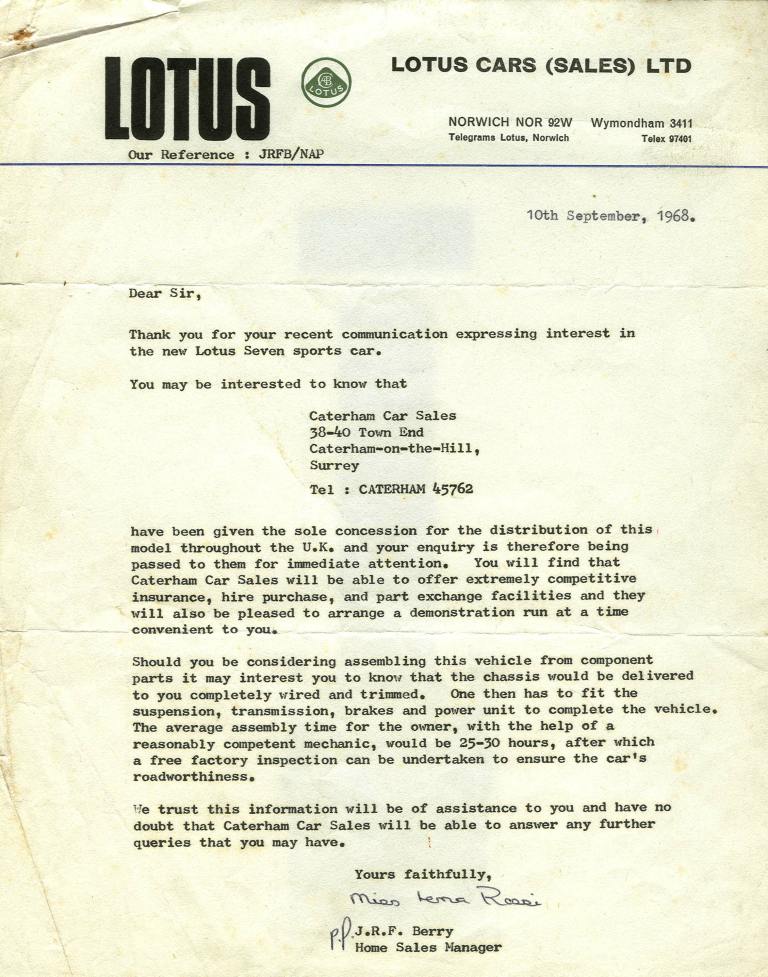
Letter announcing that Caterham Car Sales are to have sole concession.
 
AXLES STRESSES:
Unfortunately this revised method of location added a further dimension to the weakness of the axle by allowing the casing itself to carry 'twisting' stresses between the upper (side) and lower (centre) location points. The upshot of this is that, as well as half shafts breaking, the casing itself became rather less than oil tight particularly when excessive power or sticky tyre rubber were used.
 
INCREASES IN POWER:
In 1960 the Series Two was originally specified with either a 28-40bhp 1172cc. Ford side-valve or a 37-43bhp 948cc. BMC o.h.v. engine with 13" x 3˝J  steel wheels shod with skinny 520 x 13 crossply tyres. By the end of Series Two production a fairly normal top of the range factory supplied Seven had nearly three times the power and wider 4˝J wheels with radial rubber fitted and the customised cars maybe 120bhp and 5˝J or even more.
 
SOME NON-FACTORY FIXES:
Early solutions were to either change for a stronger  axle with the added expense of having to change the PCD of the front hubs as well, or by the addition of a 'Stegosaurus' strengthening plate along part or all of its length, or by changing the location method to both upper and lower trailing arms to eradicate the stress along the length of the axle.
 
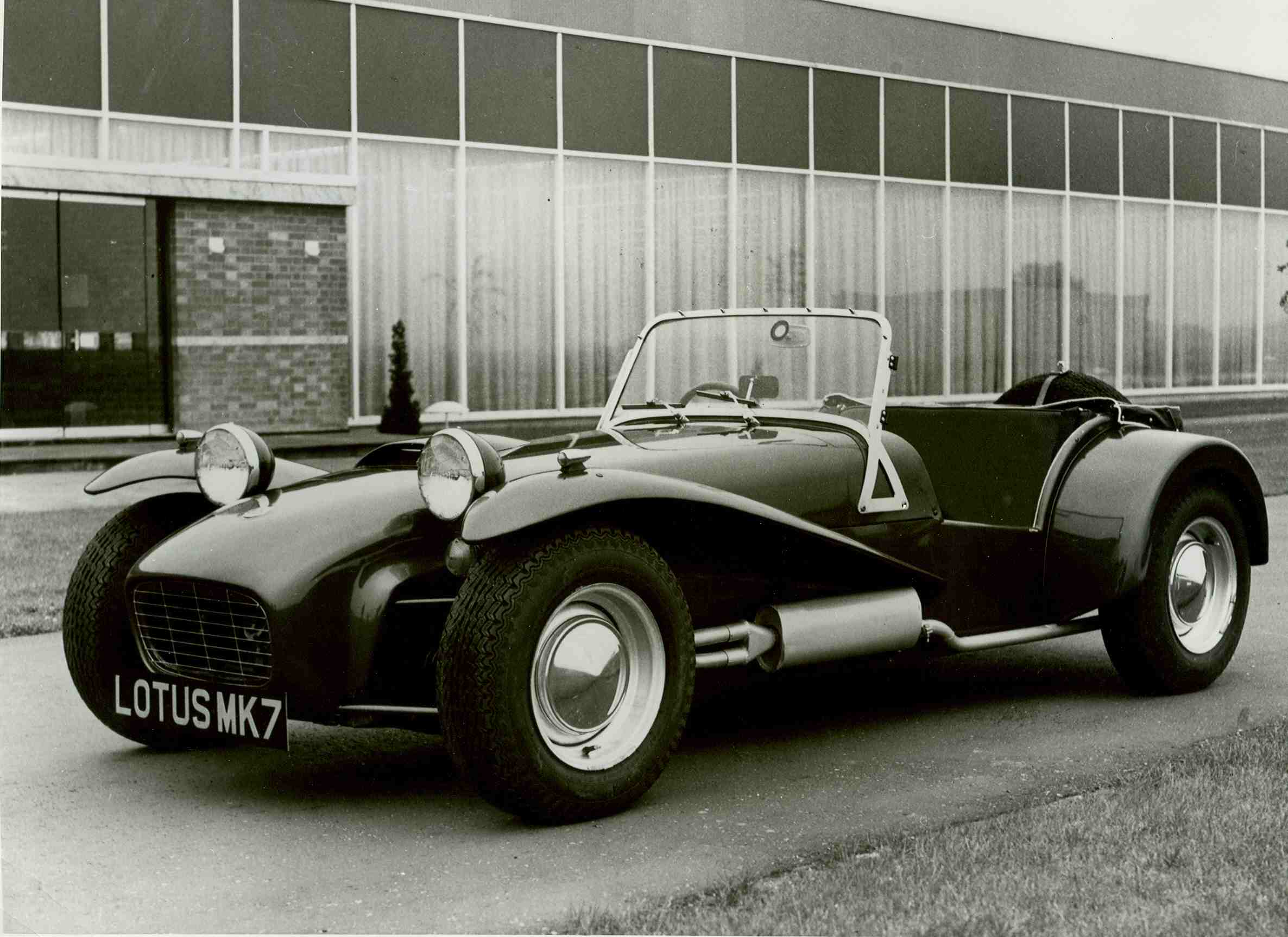
Official factory photograph taken at Hethel.
 
FIRST ‘ALL FORD’ LOTUS SEVEN
The first Series Three Lotus Seven left the factory in September 1968. The main change from the old Series Two was, as already mentioned, Ford’s 2255E crossflow engine in 1600cc or 1300cc form. In addition the relatively new ‘live’ rear axle from Ford Escort Mexico was fitted which meant larger rear drum brakes. With many Ford parts being a favourite in competitive events, this unit had advantages of increased strength, a large variety of final drive ratios and even the possibility of a limited slip differential. With the new axle, the PCD had to be regularised so that all wheels were interchangeable. This was achieved with new front hubs. With the Ford PCD came the availability of their wider 13” x 5J Ford wheels along with Dunlop 165 x 13 SP Sport HR rubber requiring the need for wider rear wings. The wheels used were the stronger variety that Lotus fitted on their Cortina and the 51 Formula Ford models. So whilst the old Series Two had Ford engine and gearbox and Standard Triumph rear axle and wheels, the new Series Three used Ford parts for all these items.
 
DIRECTION INDICATORS:
Direction indicators had been fitted to the first Seven “America” model early in 1960 and on all Series Two Sevens for export since. For these cars the front indicator lights were Lucas L1130 dual element side light / indicators with white lenses which did not comply with UK regulations. For the home market indicator lights for the Series Three were now fitted with amber lenses as standard equipment. 
 
USER FRIENDLY FUEL FILLING:
Up until now the Lotus Seven had always been a very basic car with the emphasis on light weight with no frills or pretence of luxury other than those needed by the driver, but not by the passenger! Fuel refilling had previously been achieved via the filler cap located inside the boot area which meant undoing the boot cover. For the Series Three the filler cap was located outside the boot area on the back panel of the car as it is with the Caterham today.
 
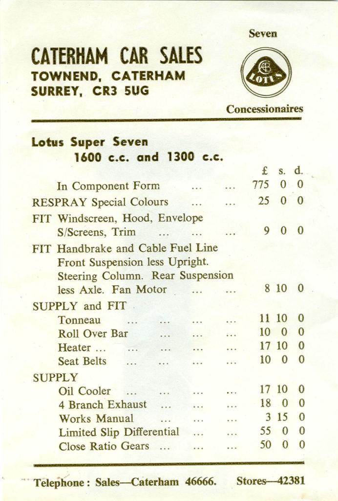
Caterham's Price List.
 
REAR EXIT EXHAUST:
For the first time on a Lotus Seven a rear exit exhaust system was fitted as standard equipment on the Series Three. Sales literature stated that this was to meet noise regulation requirements. The standard Ford cast iron manifold was used on right hand drive cars, but in order to clear the steering column, a fabricated four branch tubular steel version was needed on left hand drive cars.
 
INTERIOR LUXURY:
The traditional red of the dashboard, trim panels, seat squabs and backs were changed for black in line with other Lotus products of the day. This included ‘knitted’ pattern leathercloth for the seating, black carpeting throughout, a 14” diameter black pvc covered brushed aluminium steering wheel and black pvc bonded steel trim panels and dashboard.
 
NEGATIVE EARTH:
In line with other manufacturers and Lotus products, the electrical ground was changed from positive to negative. This would make the sourcing of electrical components much easier.     
 
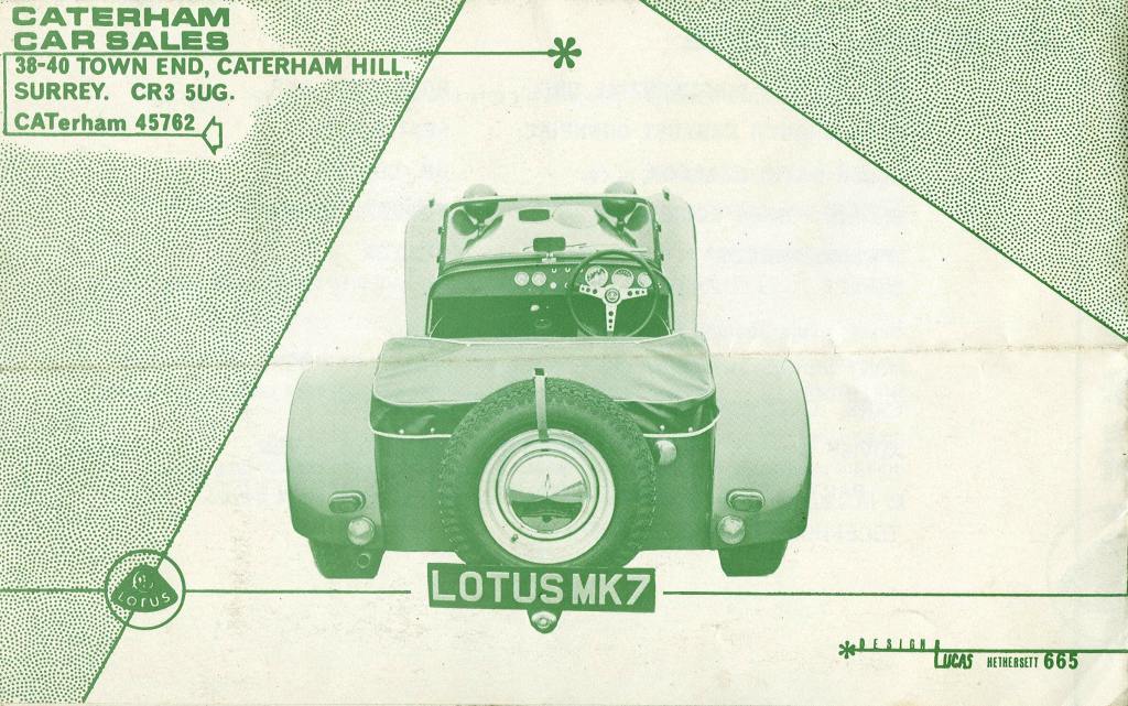
Caterham's Lotus Seven Brochure.
 
REVISED DASHBOARD LAYOUT:
Whilst all previous Sevens, with tachometers fitted, had speedometers in front of the passenger, the new car had both these Smiths instruments in front of the driver. In addition, because of the new external filler cap and the subsequent bend in the filler pipe, dipping the tank to measure fuel levels was no longer possible and an AC fuel gauge had to be included. With this extra instrument and in order to keep all instruments within view of the driver, a Smiths combined water temperature and oil pressure instrument was fitted. The Ammeter was AC in similar style to the fuel gauge.
 
NO CHANGE TO THE CHASSIS:
With all these changes to the Seven (engine, rear axle, wheels, wings, indicators, interior, etc.) the chassis remained the exactly the same in all respects except one. Up until now there was a provision for a lower rear mounting for the cycle wings which were an option on Series Two cars for most of their production period. There was no option for cycle wings with the Series Three and these brackets were omitted.
 
CHASSIS MAKERS:
The Progress Chassis Company and The Universal Radiator Company (Unirads) had made nearly all of the chassis frames for the Series Two. Towards the end of Series Two production another maker, Arch Motors, ‘came on line’ and Unirads were gradually dropped. Arch had been started in the late 1950’s by John Robinson and Don Gadd, two motorcycle sidecar racers who had made there own race frames. Whilst they did not make Seven frames until 1967, they were responsible for, amongst others, Type 22 Formula Junior and Type 23 Sports Racing cars for Lotus as early as 1962 as well as for many other companies. They were early exponents of siff-bronze welding and after much persuasion managed to convince Colin Chapman that this non-fusion method was the way to go. Arch’s involvement with the Seven continues today, nearly forty years on.
 
JWW - 19-Apr-2005
 
Coming next:
The Luxury Cars - The ‘S’ and The ‘SS’.
 
Sources and further reading:
Lotus Seven by Jeremy Coulter (1986/1995)
Lotus Seven Preparation/Restoration/Maintenance by Tony Weale (1991)
 
[previous chapter]  [next chapter]  [back to menu]